Showing posts with label GNS3. Show all posts

Friday, 22 February 2013

Juniper JNCIA-Junos - Class of Service

For this last chapter, you are going to mark some traffic.

Exercise – Marking packets

Your goal is to create a filter that you will apply on JUNOS1′s em4 interface (input). This filter will mark all packets from 10.3.3.0/24 with expedited-forwarding (EF) DSCP.

Solution

firewall {
   family inet {
        filter apply-cos {
            term from-JUNOS3 {
                from {
                    source-address {
                        10.3.3.0/24;
                    }
                }
                then {
                    forwarding-class expedited-forwarding;
                    accept;
                }
            }
            term default {
                then accept;
            }
        }
    }
em4 {
     unit 0 {
         family inet {
             filter {
                 input apply-cos;
             }
             address 172.30.25.9/30;
         }
     }
 }
This is the end of our hands-on exercises, you should now be ready to seat for the
JNCIA-Junos certification. Don’t forget you can obtain 50% off the exam cost by passing the pre-assessment exam on Juniper’s website.

Juniper JNCIA-Junos - Routing Policy and Firewall Filters

We assume you have read chapter 2 of Juniper’s second PDF so that you can practice routing policy and firewall filters. First we are going to start with a simple route redistribution followed by a firewall filter to restrict telnet access.

Exercise 1 – Default route redistribution into OSPF

Create a policy to redistribute the existing default route (0.0.0.0/0) on JunOS1 into OSPF so that other routers can use it.

Solution

[edit]
root@JUNOS1# edit policy-options
[edit policy-options]
root@JUNOS1# set policy-statement default-static term accept-default-static from protocol static
[edit policy-options]
root@JUNOS1# set policy-statement default-static term accept-default-static from route-filter 0.0.0.0/0 exact
[edit policy-options]
root@JUNOS1# set policy-statement default-static term accept-default-static then accept
[edit policy-options]
root@JUNOS1# show
policy-statement default-static {
    term accept-default-static {
        from {
              protocol static;
              route-filter 0.0.0.0/0 exact;
             }
    then accept;
    }
}
[edit policy-options]
root@JUNOS1# top edit protocols ospf
[edit protocols ospf]
root@JUNOS1# set export default-static
[edit]
root@JUNOS1# commit
JUNOS1 advertises the default route in OSPF, check that JUNOS3 can actually see it.
root@JUNOS3# run show route protocol ospf
inet.0: 15 destinations, 15 routes (15 active, 0 holddown, 0 hidden)
+ = Active Route, - = Last Active, * = Both
0.0.0.0/0          *[OSPF/150] 00:00:05, metric 0, tag 0
> to 172.30.25.9 via em4.0

Juniper JNCIA-Junos - Routing Fundamentals

Starting with Juniper’s second PDF, we can make a new practice lab for the next 3 chapters. This lab is a bit more advanced than the previous one in order to test the OSPF routing protocol. You will need 3 Juniper routers, here are the connections:
  • JUNOS1, interface em0 <-> JUNOS2, interface em0
  • JUNOS1, interface em1 <-> JUNOS2, interface em1
  • JUNOS1, interface em4 <-> JUNOS3, interface em4
  • JUNOS2, interface em3 <-> JUNOS3, interface em3
Make sure the routers have a factory default configuration (use the load factory-default command if you need to). Then set the host-name, root password and IP addresses for each router, to save time you can copy and paste the following commands (don’t forget to commit):

JUNOS1

set system host-name JUNOS1
set interfaces em0 unit 0 family inet address 172.30.25.2/30
set interfaces em1 unit 0 family inet address 172.30.25.6/30
set interfaces em3 unit 0 family inet address 192.168.1.1/24
set interfaces em4 unit 0 family inet address 172.30.25.9/30
set interfaces lo0 unit 0 family inet address 10.1.1.1/24
set system root-authentication plain-text-password

Juniper JNCIA-Junos - Operational Monitoring and Maintenance

For the last chapter of Juniper’s first PDF, we are going to have a closer look how to get more information about JunOS and also practice the password recovery procedure that will sooner and later be useful for you.

Exercise 1 – boot messages

Do you remember the booting process in chapter 1? Well you have a command to see the messages again (hint: use the show system command).

Solution

root@JUNOS1# run show system boot-messages
Copyright (c) 1996-2010, Juniper Networks, Inc.
...
ad1: 1024MB <QEMU HARDDISK 0.11.0> at ata0-slave WDMA2
Trying to mount root from ufs:/dev/ad0s1a
vn_read_compressed_block: invalid block index 550

Juniper JNCIA-Junos - Secondary System Configuration

Before diving deeper into JunOS configuration you should have read chapter 4 of Juniper’s first PDF. Let’s continue with the same lab as before.

Exercise 1 – Syslog

On JUNOS2, set up a syslog file to record any config changes (hint: system syslog). Commit and quit.

Solution

[edit]
root@JUNOS2# set system syslog file config-changes change-log info
[edit]
root@JUNOS2# commit and-quit
commit complete
Exiting configuration mode
Now go back to configuration mode and change junuser to give operator permissions instead of super-user. Again, commit and-quit. Using the show command, display the log related to your previous commit.

Solution

[edit]
 root@JUNOS2# set system login user junuser class operator
[edit]
root@JUNOS2# commit and-quit
commit complete
Exiting configuration mode
root@JUNOS2> show log config-changes
 Dec 16 05:06:24  JUNOS2 mgd[1392]: UI_CFG_AUDIT_SET: User 'root' set:
[system login user junuser class] "super-user -> "operator"
Use the help syslog command to learn more about the message code (UI_CFG_AUDIT_SET).

Wednesday, 20 February 2013

Juniper JNCIA-Junos - User Interface Options & Initial Configuration


This page is to practice what you learned in Juniper’s PDF (part 1), chapter 2 and 3.  So now it is time to get active and log in as root without any password.
First thing you should notice is that Amnesiac is the default host-name. This indicates that our JunOS is running with the factory-default configuration (you can use the load factory-default command in configuration mode to have a JunOS in this state).
You are logged in as root, you should see the UNIX shell prompt root@% where you can type UNIX commands like ls or ps but this is beyond our scope. What we want is the operational mode prompt root> that is started with the cli command.
Amnesiac (ttyd0)
 login: root
--- JUNOS 10.1R1.8 built 2010-02-12 17:15:05 UTC
 root@% cli
 root>
Type show configuration to display the current factory-default configuration.
root> show configuration
## Last commit: 2011-02-17 00:34:21 UTC by root
version 10.1R1.8;
system {
    syslog {
        user * {
            any emergency;
        }
        file messages {
            any notice;
            authorization info;
        }
        file interactive-commands {
            interactive-commands any;
        }
    }
    ## Warning: missing mandatory statement(s): 'root-authentication'
}
Note the missing mandatory statement warning, this means you will not be able to commit your changes until you set up a password for root.

Juniper JNCIA-Junos - Operating System Fundamentals

This part is mainly theory and reading chapter 1 of Juniper’s PDF (part 1). It is only what you need for the exam; however, it is interesting to have an overview of how JunOS actually boots up.
First, make your lab in GNS3 by connecting 2 routers back to back using their em0 interface. Keep this lab for all your exercises for chapters of part 1.
Start your Juniper routers in GNS3 and console to them. As you learned in Juniper’s PDF, JunOS is based on FreeBSD, an open source UNIX Operating System. This OS is very reliable and you also get extra tools that you cannot find on Cisco IOS for instance.
The first thing you should see after starting JunOS, are the kernel modules being loaded. The kernel is the core component of the operating system.
/boot/modules/if_bge.ko text=0xa98c data=0x364+0xc syms=[0x4+0xd50+0x4+0xd18]
...
/boot/modules/mac_runasnonroot.ko text=0x7b4 data=0x4d0 syms=[0x4+0x310+0x4+0x39d]
Then, you have a chance to give parameters to the kernel in order to change the default booting process. This can be useful to recover the root password for example, but that’s not the only use. Root is the name given to the super administrator on UNIX.

Tuesday, 15 January 2013

GNS3 Installation Hypervisor Load Balancing - 2

PART 7: START GNS3 ON THE SERVER AND CREATE SIMPLE TOPOLOGY


GNS3 Installation Hypervisor Load Balancing - 1

THIS PROCEDURE MADE UP WITHIN MULTIPLE PARTS:

1. Directory structure 2. GNS3 configurations
3. Configure Hypervisor
4. Edit Dynamips on the client
5. Edit Dynamips on the Server
6. Start Dynamips on SVR and Client
7. Start GNS3 and create simple topology


PART 1: DIRECTORY STRUCTURES
Step 1: Directory to work with… etc.
let’s create some directories in the server, remote PC and call it “GNS3”
Server: C:\GNS3 and remote pc(s): C:\GNS3
Step 2: Image directory… etc.
Server: C:\GNS3\images\ and remote pc(s): C:\GNS3\images\
Copy all the images you are planning use to both directories
Step 3: Folder for “work area” … etc.
Server: C:\GNS3\workarea\ and remote pc(s): C:\GNS3\workarea\
Step 4: Folder for router initial configurations… etc.
Server: C:\GNS3\inital_config\ and remote pc(s): C:\GNS3\inital_config\
Step 5: Folder for Dynamips work area… etc.
Server: C:\GNS3\workarea\dynamips-work-dir\ and remote pc(s): C:\GNS3\workarea\dynamips-work-dir\
Step 6: Folder for your project directory… etc.
Server: C:\GNS3\workarea\project-dir\ and remote pc(s): C:\GNS3\workarea\project-dir\
Step 7: Folder for capture directory… etc.
Server: C:\GNS3\workarea\wireshark\ and remote pc(s): C:\GNS3\workarea\wireshark\
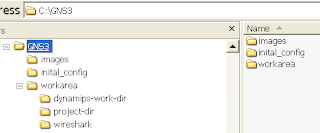
Your directory should look like this or what is best works for you…


PART 2: CONFIGURE GNS3
Step 1: Configure Preferences General… etc.
Select  -- >   Edit -->   Preferences


Select--> General, fill out the required fields apply, OK


Step 2: Configure Preferences Dynamips; fill out the required fields, test, apply and OK.


 Step 3: Configure Preferences Capture; fill out the required fields apply, OK.


Step 4: Configure hypervisor…… etc.
Select; Edit IOS images and hypervisor


Select the image file, platform, model and uncheck default image… box and leave rest default, apply, OK.


PART 3: CONFIGURE HYPERVISOR
Step 1: Configure hypervisor… etc.
Select; Edit IOS images and hypervisor and click on “External Hypervisor” tab
Host: Your remote PC, to add more host, simply follow same steps, change IP, Port, UDP and console port
Note: XP SP2 or SP3 users; either turn of your firewall or create exceptions for dynamips and ports!
Select; Start Control Panel Windows Firewall; click on Exception tab. Click on “Add Program” for dynamips and
click on “Add Port”
After filling out rest of the fields, click on “save” and click on “IOS Images” tab


PART 4: EDIT DYNAMIPS FILE ON THE CLIENT
Step 1: Remote or login the remote PC and Start Run type “C:\Program Files\GNS3\”
Find “dynamips-start.cmd” edit with your favorite editor;
Change line five where it says 7200 to 7220

Recommend creating a shortcut for “dynamips-start.cmd” to on your desktop, because your going to use this quite frequently because everything
stop the router, you need to shutdown and restart it 


PART 5: EDIT DYNAMIPS FILE ON SERVER


Step 1: Remote or login the remote PC and Start Run type “C:\Program Files\GNS3\”
Find “dynamips-start.cmd” edit with your favorite editor;
Change line five where it says 7200 to 7221


PART 6: START DYNAMIPS ON SERVER AND CLIENT
Server:

Step 1--> Double on dynamips shortcut on the server’s desktop;
Clients:
Step 2 --> Double on dynamips shortcut on the remote PC’s desktop


How To: Use MRTG with GNS3

What is MRTG?

  • MRTG is opensource program which gets traffic statistics from devices using SNMP and builds graphs like this:

Installing MRTG

Setup virtual topology

In this case we wan’t to make most simple example so we are using only one router:
  •  Install Ms loopback adapter to your Windows machine and configured IP-address 10.10.10.1/24 for it.
  • Configure router:
hostname R0
!
interface FastEthernet1/0
ip address 10.10.10.2 255.255.255.0
duplex auto
speed auto
!
!
!
snmp-server community mycommunity RO
Verify that ping goes from your local computer to emulated router R0

Configure and run MRTG

  • After you have configured MRTG with command:
perl cfgmaker mycommunity@10.10.10.2 –global “WorkDir: c:\www\mrtg” –output mrtg.cfg
  • Run MRTG with command:
perl mrtg mrtg.cfg
Every time when you run MRTG it will get data from the router and save it. You can run MRTG manually every 5 minutes or configure this to happen automatically. To do this follow MRTGinstructions. When you have done this MRTG starts to build graph for you.

[Video] - Step By Step Guide To Install JunOS on GNS3

Note: Steps by Steps video guide to install JunOS 10.1 in Qemu for GNS3 for Juniper router simulation can be viewed at the end of this post.
Download the required software
1. JunOS 10.X (use Torrents may OS Image are available from there i also got)
Link
2. Download FreeBSD 4.11 as base OS for Router Download
3. Download Qemu 0.11.0 from GNS3 web site Download
4. Need to Software to create CD ISO image. ex:
Deep Burner

Time to Start
Step 1: Download all the given files above
Step 2: Extract Qemu in a folder
Step 3: Open cmd and navigate to extracted folder
Step 4: Create a HDD image to install JunOS of 4GB

qemu-img.exe create j.img -f qcow2


Step 5:
Start the Qemu with Free BSD CD and Created HDD

qemu.exe -L . -m 256 -hda j.img -boot d -localtime –cdrom ..\4.11.4.11-RELEASE-i386-miniinst.iso


Step 6:
Install Free BSD in Qemu
Skip Kernel configuration
Choose standard installation
With fdisk, press A to allocate entire disk for bsd
Select: install a standard MBR
Create partition (with C)
512M for /
1024M for swap partition
128M for /config
and the rest for /var
Choose installation type: user, and select No for FreeBSD ports
X to Exit the menu and install from CD/DVD
Wait until it's done
Yes for chance to set any last options
Type root password
Select 'X' to Exit the installation, it will reboot
while it's rebooting, exit from Qemu by pressing Ctrl-Alt-2,
then type: q

Step 7:
Make JunOS ready to transfer in guest OS
Create a CD Image (ISO) of junOS (using deepburner or any of it kind) and save in Qemu Folder with name like j8.iso
 

Step 8:
Make JunOS Ready for Installation

qemu -L . -m 512 -boot c -hda j.img –cdrom j8.iso

We need to untar the signed jinstall file first:


#mount /cdrom
#cd /var/tmp
#mkdir junos
#cd junos
#tar zxvf /cdrom/jinstall-10.1R1.8-domestic-olive.tgz
Then untar the unsigned image:
#mkdir jinst
#cd jinst
#tar zxvf ../jinstall10.1R1.8-domestic.tgz
Extract the pkgtools.tgz file and replace the checkpic binary inside with /usr/bin/true :
#mkdir pkgtools
#cd pkgtools
#tar zxvf ../pkgtools.tgz
#cd bin
#cp /usr/bin/true ./checkpic
#cd ..
Create tar for pkgtools then remove the directory:
#tar zcvf ../pkgtools.tgz *
#cd ..
#rm -rf pkgtools
Create tar for the new jinstall package with modified checkpic
#tar zcfv /var/tmp/j.tgz *
Then install the new jinstall with bsd pkg_add tool:
#pkg_add -f /var/tmp/j.tgz


It will ask to reboot to continue the installation.
One installation is finished and prompt is returned press Crtl+Alt+2 then type “q” press enter

Step 9:
Install JunOS in Guest VM

“qemu -L . -m 512 -hda j.img -serial telnet:127.0.0.1:1001,server,nowait,nodelay –localtime”

open new cmd and do telnet to 127.0.0.1 to enjoy the watching installtion process of JunOS
Once Prompt appear type cli to start junOS configuration

Step By Step Guide To Install JUNOS on GNS3 [Part 3]

Updating JunOS
You can update your version of JunOS from the CLI with the following command:

request system software add [jinstall_package]


Running your router(s)
Now you have a base olive image. Qemu allows you to use this as a base for other images and only writing the changes to your “slave” images saving on disk space! You can also use less memory for each Qemu instance.
Create a new image off of your base image. Repeat for all your routers you want to emulate:

qemu-img create -b olive-base.img -f qcow2 R1.img

Start your router and then telnet to it:

2001 Once logged in, you can type “cli” to launch the JunOS command line interpreter, exit to … exit and halt to shutdown FreeBSD. Remember to kill your qemu instance(s).

qemu R1.img -m 96 -nographic -daemonize -serial telnet::2001,server,nowait \
-localtime -net nic,macaddr=00:aa:00:60:01:01,model=e1000 -net user telnet localhost


Networking your routers
Ok, one router it’s cool but useless alone. It’s time to make your virtual network! There are many ways to network your olive routers.


Olive to Olive using UNIX sockets
UNIX sockets create a TCP stream between two Qemu instances with one a client and the other a server. Apparently this method creates duplicate packets sometimes.

qemu R1.img -m 96 -nographic -daemonize -serial telnet::2001,server,nowait \
-localtime -net nic,vlan=1,macaddr=00:aa:00:60:01:01,model=e1000 \
-net socket,vlan=1,listen=:6000

qemu R2.img -m 96 -nographic -daemonize -serial telnet::2002,server,nowait \
-localtime -net nic,vlan=1,macaddr=00:aa:00:60:01:02,model=e1000 \
-net socket,vlan=1,connect=127.0.0.1:6000


Olive to Olive using UDP tunnels
UDP tunnels are mainly used to connect to Dynamips/GNS3 emulated routers but can also be used as a more reliable way to connect two Qemu olives together but this can result in much lower latency connections as well.

Olive to real world using TAP interface
One way to connect an interface on your Olive with a real Ethernet NIC is to use a bridge and the Qemu tap option.

Linux:
It is required that you have the generic TUN/TAP driver either built-in to your kernel, or available as a module. To check the availability of this module do the following:

ls -la /dev/net/tun

If you get no such file or directory, try doing a modprobe tun. It should then appear in the

lsmod output.

One way to connect an interface on your Olive with a real Ethernet port is to use a bridge and the net -tap option. This requires you to have the generic TUN/TAP driver either built-in to your kernel, or available as a module. To check the availability of this module do the following:

Let’s say you started the emulator with the following:

qemu R1.img -m 96 -nographic -daemonize -serial telnet::2001,server,nowait \
-localtime -net nic,vlan=1,macaddr=00:aa:00:60:00:01,model=e1000 \
-net tap,vlan=1,script=no


Note the vlan=1 and -net tap options. This basically connects your Olive’s en0 to a virtual tap interface (usually tap0) on your host system. Start up Qemu, and once the emulator is running, proceed to the next step. You’ll need to start up the emulator as root, or change the ownership or permissions on /dev/net/tun.
We’re going to need to now bridge the tap0 interface to another Ethernet interface on the host system. To do this, we’ll utilize the bridge capabilities of Linux. First, get the bridge utilities:

sudo apt-get install bridge-utils


Let’s assume you want to connect en0 on the Olive to eth1 on the host system.

Do the following as root:

brctl addbr br0
brctl addif br0 eth1
brctl addif br0 tap0


This creates a bridge device, br0, and binds the two interfaces to it. Right now everything is still down. Let’s bring it up…

ifconfig eth1 up
ifconfig tap0 up
ifconfig br0 up


Now the bridge and member interfaces should be up. Don’t assign any IP addresses to either of the member interfaces. If you want to, you can assign something to br0 if needed. (br0 is analogous an SVI in the Cisco world) To see the status of the bridge, do the following:

brctl show
bridge name bridge id STP enabled interfaces
br0 8000.000cf19ce06c no eth1
tap0


Now, assign an IP address to the em0 interface on your Olive, and it should be online. You are also free to tcpdump on the bridge or member interfaces, for debugging. All of this can probably be put into a Qemu interface script, so you can remove the script=no option, and make it a little more automatic.
Your kernel might have ethernet filtering (ebtables, bridge-nf, arptables) enabled, and traffic gets filtered except ARP and STP. The easiest way to disable this is to go to /proc/sys/net/bridge. Check if the bridge-nf-* entries in there are set to 1; in that case, set them to zero and try again. More information on bridges available
here.

# cd /proc/sys/net/bridge
# ls
bridge-nf-call-arptables bridge-nf-call-iptables
bridge-nf-call-ip6tables bridge-nf-filter-vlan-tagged
# for f in bridge-nf-*; do echo 0 > $f; done


Windows:

Using OpenVPN you can create several tap interfaces with “Add a new TAP-Win32 virtual Ethernet adapter” and rename them with something like ‘Tap1′, ‘Tap2′ and so on Let’s say we have created 1 Tap interface and renamed it as Tap1. Right click this Tap1 interface on Windows Control Panel – Network Connections and give IP address for example 10.1.1.1/8.
Now you can start Qemu with the -net tap option and ping the interface from your Olive:

qemu -L . -m 96 -hda R1.img -localtime \
-net nic,vlan=1,macaddr=00:aa:00:60:01:01,model=e1000 \
-net tap,vlan=1,ifname=tap0
 

Mac OS X

On Mac OS X, download and install the TunTap package.

qemu R1.img -m 96 -nographic -daemonize -serial telnet::2001,server,nowait \
-localtime -net nic,vlan=1,macaddr=00:aa:00:60:00:01,model=e1000 \
-net tap,vlan=1,ifname=tap0,script=no
 

We need to give this inter face an ip address:

sudo ifconfig tap0 198.18.0.250/24 up


Olive to real world using PCAP/LACP
In the patch provided in this howto, there is an option to use PCAP or LCAP libraries to bridge directly to a physical interface. You will probable need to run Qemu under Administrator privileges. Please also note that it will stop any other traffic on your interface.

For PCAP:


 qemu R1.img -m 96 -nographic -daemonize -serial telnet::2001,server,nowait \
-localtime -net nic,macaddr=00:aa:00:60:01:01,model=e1000 \
-net pcap,ifname=eth0


For LCAP:

 qemu R1.img -m 96 -nographic -daemonize -serial telnet::2001,server,nowait \
-localtime -net nic,macaddr=00:aa:00:60:01:01,model=e1000 \
-net lcap,ifname=eth0
 

Please note that you have to configure an IP address your physical interface before being able to communication between your routers. Also I didn’t test PCAP/LCAP on Windows.

Olive to Dynamips or Pemu

The lastest patch also added a udp option to allow networking to a Dynamips or pemu.

qemu R1.img -m 96 -nographic -daemonize -serial telnet::2001,server,nowait \
-localtime -net nic,vlan=1,macaddr=00:aa:00:60:00:01,model=e1000 \
-net udp,vlan=1,sport=10000,dport=10001,daddr=127.0.0.1
 

Then in your dynagen .net file

[[router Cisco1]]
fa0/0=NIO_udp:10001:127.0.0.1:10000


Olive to GNS3
Under GNS3, you can create a “Cloud” and configure a NIO UDP (you can add as many NIO UDP as you want). The “Cloud” will be your interface between Olive and GNS3, you can link a firewall or a router per NIO UDP.


Of course, you can do the same with other NIOs like NIO TAP to connect to yourolive using a TAP interface.

Testing
To check if everything work, let’s configure 2 Olives:

root@%cli
root>edit
[edit]
root#

[edit]
root#set system root-authentication plain-text-password
New password:
Retype new password:

[edit]
root#set interfaces em0 unit 0 family inet address 10.0.0.1/8
[edit]
root#commit
commit complete

Configure the other device using the same commands but with another IP address (e.g. 10.0.0.2/8) and ping.

root#exit
Exiting configuration mode
root> ping 10.0.0.2
PING 10.0.0.2 (10.0.0.2): 56 data bytes

64 bytes from 10.0.0.2: icmp_seq=0 ttl=64 time=9.771 ms
64 bytes from 10.0.0.2: icmp_seq=1 ttl=64 time=0.614 ms
64 bytes from 10.0.0.2: icmp_seq=2 ttl=64 time=0.693 ms
64 bytes from 10.0.0.2: icmp_seq=3 ttl=64 time=0.630 ms


Additionally, configure OSPF (or any other multicast based protocol) to test if your routers can talk to each other using multicast packets. Again, type those commands on both routers:

root# set protocols ospf area 0 interface em0

[edit]
root# commit
commit complete

[edit]
root# exit
Exiting configuration mode

Then monitor the traffic from one of the router, you should see some multicast traffic (from/to 224.0.0.5):

root> monitor traffic interface em0

02:30:30.973748 Out IP 10.0.0.1 > 224.0.0.5: OSPFv2, Hello, length 48
02:30:31.007675 In IP 10.0.0.2 > 224.0.0.5: OSPFv2, Hello, length 48


Is everything working? yes? then you are successfully running JunOS! Happy networking

What is working
Here is a list of what has been tested and works. You can extend this list by posting comments on what is working or not for you and I’ll update the list:

                                                OSPF (fxp0) OK                            
                                                OSPF (em0) OK                            


A few words about the patch By default using JunOS with a non-patched Qemu, multicast based protocols didn’t worked. As I have very little driver coding experience (and time to learn), I patched Qemu to allow multicast frames to be received by JunOS, instead of being filtered at the driver level multicast frames are filtered by JunOS. The only problem I see could be on the performance side, as JunOS receives every multicast frames, even those not destined to it. However, I think this is not an issue for a simulated lab environments and it worked just fine so far.
If you feel you can do something cleaner, please don’t hesitate, you can still read one of the
Intel manuals concerning the e1000 to have an overview of how complicated driver programming can be.

Conclusion
If you are IT guy (hope you are if you want to play with JunOS), you should be able to run JunOS on your PC without too many issues. I wrote this howto to be as complete as possible, showing how to compile and patch Qemu on 3 different operating systems, installing FreeBSD and JunOS. I encourage everyone to contribute to it by providing fixes, comments or any other help.